Privacy statement: Your privacy is very important to Us. Our company promises not to disclose your personal information to any external company with out your explicit permission.

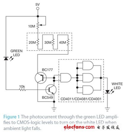
The LED can be used as a photoelectric sensor. There was a design idea that gave a high-power-efficiency switch that consumes almost no power. However, this structure cannot be adjusted to switch to the desired light intensity. The circuit in this design idea can be adjusted to any light intensity threshold level that keeps the photoelectric switch in an on-state, and the power consumption is almost the same as the original circuit (Figure 1).

Figure 1 The photocurrent is amplified to the CMOS logic level by the green LED, and the white LED is illuminated when the ambient light drops.
Ambient light illuminates the reverse-biased green LED, producing a small current through the LED that forms the base current of the BC549 NPN transistor, which is amplified and sent to the base of the BC177 PNP transistor. This current is then amplified and passed through the emitter of BC177. The voltage drop across the emitter resistor depends on its resistance and the current flowing through it, which determines the voltage drop across the CE terminal of BC549.
By adjusting the value of the emitter resistance in series, a voltage relative to the logic 0 of the CMOS gate can be set for any intensity light that is illuminated on the green LED. This light intensity depends mainly on the response of the green LED and the current gain of the two transistors. Therefore, when selecting the resistance value, the series resistors are combined for various short circuits, and the 10-MΩ potentiometer is used for fine adjustment. Once the appropriate value is found, the useless resistor can be removed from the circuit.
When the ambient light intensity is below this level, the base current of BC549 and the current through the emitter series resistor are both reduced. This drop raises the input voltage of the CD4011 logic gate above the CMOS switching threshold. At 3V output, a typical gate output current is approximately 3-4 mA/gate; three gates in parallel provide approximately 10 mA to the white LED. The same result can be obtained with an inverting gate or a non-inverting gate. The reason the circuit still maintains its power efficiency is that the series resistance values typically required exceed 10 MΩ.
The suitability of the green LED as a photocell can be checked by measuring the voltage drop across the LED using a digital multimeter 200 mV. If the LED is suitable as a photosensor, the measurement is a voltage of 0.3 to 1 mV and this voltage will vary with the intensity of the light on the LED.
November 04, 2024
November 04, 2024
November 06, 2024
November 01, 2024
이 업체에게 이메일로 보내기
November 04, 2024
November 04, 2024
November 06, 2024
November 01, 2024

Privacy statement: Your privacy is very important to Us. Our company promises not to disclose your personal information to any external company with out your explicit permission.

Fill in more information so that we can get in touch with you faster
Privacy statement: Your privacy is very important to Us. Our company promises not to disclose your personal information to any external company with out your explicit permission.