


Please Leave Us A Message
Privacy statement: Your privacy is very important to Us. Our company promises not to disclose your personal information to any external company with out your explicit permission.

1 Introduction
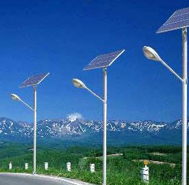
Solar street lights are mainly composed of four parts: solar photovoltaic modules, batteries, charge and discharge controllers, and lighting fixtures. The bottleneck in the popularization of solar street lamps is not a technical issue, but a cost issue. In order to improve the stability of the system and maximize the performance on the basis of cost reduction, it is necessary to properly match the output power of the solar cell and the battery capacity and load power. For this reason, only theoretical calculations are not enough. Because the solar light intensity changes rapidly, the charging current and the discharging current are constantly changing, and the theoretical calculation will bring a large error. Only by automatically tracking and monitoring the charge and discharge current can accurately determine the maximum power output of the photocell in different seasons and different orientations. In this way, the battery and the load are determined to be reliable.
On the LabVIEW software platform, combined with the data acquisition card, virtual instrument technology can be used to achieve automatic monitoring and data analysis tasks. This article describes the monitoring system developed by ourselves.
2 design principles
The conditioning circuit is used to sample the output current of the photovoltaic cell, the discharge current of the battery, and the charging and discharging working voltage of the battery at a certain frequency, and the collected data is sent to the computer by the USB data acquisition module. Timely display and statistical analysis on the LabVIEW software platform. The principle block diagram is shown in Figure 1.

Figure 1 system block diagram
3 data acquisition hardware configuration
3.1 conditioning circuit
The battery output signal is a floating signal. Using differential measurement minimizes the impact on the circuit under test and also reduces measurement errors. In this conditioning circuit, a differential amplifier fabricated using an integrated operational amplifier ICL7650 with high precision and low drift is used as a current detection signal for a differential signal that is connected to a precision small resistor connected to a charging and discharging line. The small signal obtained by the large resistor divider incorporated into the battery is used as the voltage signal. In order to eliminate the interference, two equivalent resistors are respectively connected between the two input terminals of the differential amplifier and the signal ground. The output signals of the two differential amplifiers are sent to the two input channels of the USB acquisition module to complete signal conditioning and acquisition. The conditioning circuit is shown in Figure 2 and Figure 3.

Figure 2 current signal conditioning

Figure 3 voltage signal conditioning
3.2 data acquisition module
This system adopts the USB connection 1:3 data acquisition module produced by HYTEK of Canada, the model is iUSBDAQ-U120816. Although it is not a high-end acquisition card, it is enough to achieve the end of the collection when collecting DC signals, especially when the sampling frequency is not very high. After that, select the "Exit and Playback" button and the capture waveform will be displayed in the playback waveform window. The USB interface is easily used for hot plugging and plug and play. Connect to a laptop for on-site data monitoring.
3.3 module configuration and drive
The acquisition module can be activated by executing the device driver iUSBDAQ-Driver.exe provided by HYTEK on the computer used. Then copy the iUSBDAQ_ALL_Vis.LLb dedicated VI function library provided by the company to the User subdirectory under the vl subdirectory of the LabVlEW7.1 directory, and call User Functions and User Controls in the BlockDiagramt and Front Panel editing environment.
4 software development
LabVIEW is a graphical programming language developed by National Instruments (NI), which is widely used in instrument control, automated testing, data analysis and processing. It is an excellent development of virtual instrument software. It is widely used in the field of automated measurement and control. This system was developed using the LabVIEW 7.1 version.
4.1 program flow chart (see Figure 4)

Figure 4 program flow chart
4.2 panel design
In the panel diagram shown in Figure 5, two switches are provided to select whether to monitor current, voltage or simultaneous monitoring. The current real-time acquisition curve and the voltage real-time acquisition curve are respectively displayed and displayed with a digital display. In the acquisition cycle setup window, set the sampling period in seconds. The "Start Acquisition" button has a pause function. After all the acquisitions are completed, select the "Exit and Playback" button. The waveform of the acquisition current will be displayed in the playback waveform window, and the area under the curve will be calculated as the number of hours (energy value) of the current charge and discharge. A list of all data with date and time information is displayed at the bottom right of the panel, and the current and voltage maximum and minimum values are displayed.

Figure 5 virtual instrument panel diagram
4.3 program structure description
The overall use of two frames of the Flat Sequence structure (Flat Sequence), the first frame is completed data acquisition and display, storage; the second frame completes the data calculation, recovery and display operation results. Figure 6 shows the first frame graphics program.

Figure 6 first frame graphical block diagram
The frame uses a Timed Loop structure. Before entering the loop structure, use OpetdCreate/Replace File VI to create the path and file name of the data file ( .txt) to be stored , and call the iUSBDAQ_0penDevice function to open the acquisition device. When you choose to start collecting the branch structure, the two input channels of the acquisition device will be turned on to collect data in turn to obtain a two-dimensional array. The array is separated by the Delete From Array function, and is used as a current and voltage selection switch through two branch structures, and is sent to the waveform by numerical scaling. Chart. Outputs the date and time information of Format Date/TimeString and the string output of two arrays converted by Number To FractionalString. It is merged by Concatenate Dtrings and sent to the specified disk data file via Write File VI for analysis and call.
When the "Pause Acquisition" or "Exit Acquisition" button is selected, the loop should be quickly exited regardless of the setting of the acquisition cycle. To this end, an algorithm for judging the number of cycles and the number of acquisitions is employed.
Number of acquisitions = number of cycles / collection cycle.
The result of the divisibility is the number of acquisitions, and the remainder is used as the judgment condition for the end of one acquisition. The two branching structures can be used to accumulate the number of intermittent acquisitions until the timing loop is selected. Since the set timing cycle is 1 second, the cycle always runs in a 1 second cycle regardless of the acquisition state. When the "Exit Acquisition" button is pressed, the maximum waiting time is 1 second to exit, instead of waiting for a sampling period set by the user.
At the end of the acquisition of the data, before exiting the first frame structure, close the file via the Close File VI and shut down the device via iUSBDAQ-Release Defice. Figure 7 shows the second frame graphics program.

Figure 7 second frame graphical block diagram
The frame is first read from the data in the disk data file by the Read Characters From File VI function. Since the string is read, it is converted to a three-dimensional array by the Spreadsheet StringTo Arrary function, and then separated into three one-dimensional arrays by two Delete From Array. The current information data is sent to BuildWaveform to generate a waveform, which is displayed by Chart. At the same time, the set of data is integrated by Numeric Integration.vi, and the area under the curve is obtained, and the number of hours of charge and discharge is displayed in the output energy window.
While playing back the current curve, the sample data of each time is displayed in the String window list of the screen. The current and voltage information array is then found by Reshape Array and Array max&min to find the maximum and minimum values.
5 Conclusion
Using LabVlEW software and USB acquisition module combined with the virtual instrument developed, the whole process of battery charging and discharging of solar street lamps is well completed.
The operation is simple, the interface is friendly, and the measurement data has high precision. Data that is difficult to obtain with ammeter and voltage form measurements is obtained. Increased measurement efficiency and saved instrument costs. The measured data can reasonably match the output power of the solar cell and the capacity of the battery and the load to maximize the benefits. At the same time, it has practical significance to extend the service life of the battery, increase the brightness of the street lamp and reserve the energy of the continuous rainy day.
This system also has application value for other electric charging batteries. On this basis, the control unit can be further developed, and the LabVlEW PID tool kit can be used to automatically control the battery overcharge, over discharge, short circuit, reverse charge and time switch.
The above content is provided by WOSEN. WOSEN is a professional manufacturer and supplier of Led Flood Light, Led Street Light, Led Solar Light, etc. For more information, please visit https://www.wosenled.com/ or contact admin@wosenled.com or WhatsApp +86-13425434349

September 29, 2024

September 29, 2024

October 28, 2024

October 26, 2024
August 11, 2023

August 11, 2023
이 업체에게 이메일로 보내기
September 29, 2024
September 29, 2024
October 28, 2024
October 26, 2024
August 11, 2023
August 11, 2023
Privacy statement: Your privacy is very important to Us. Our company promises not to disclose your personal information to any external company with out your explicit permission.
Fill in more information so that we can get in touch with you faster
Privacy statement: Your privacy is very important to Us. Our company promises not to disclose your personal information to any external company with out your explicit permission.